We’ve recently noticed strange things happening when connecting/re-connecting to the control board during an experiment (e.g., drops randomly moving on the device, electrolysis, etc.), and while testing out the new hardware calibration routines (e.g., several fried op-amps in the feedback circuit). We hooked up an oscilloscope to the system and ran some tests to figure out what was going on.
When you initiate a connection to the DropBot (e.g., by launching the Microdrop application), the control board pulls a pin on the ATX power supply low to turn it on. This provides power to the daughter boards (e.g., the signal-generator board and high-voltage switching boards), which then power-up and initialize. During the power-up of the signal-generator board, transient voltages appear on the output pin within the first ~200 ms; if the amplifier is on during this time, it can output voltages in excess of +/- 200 V.
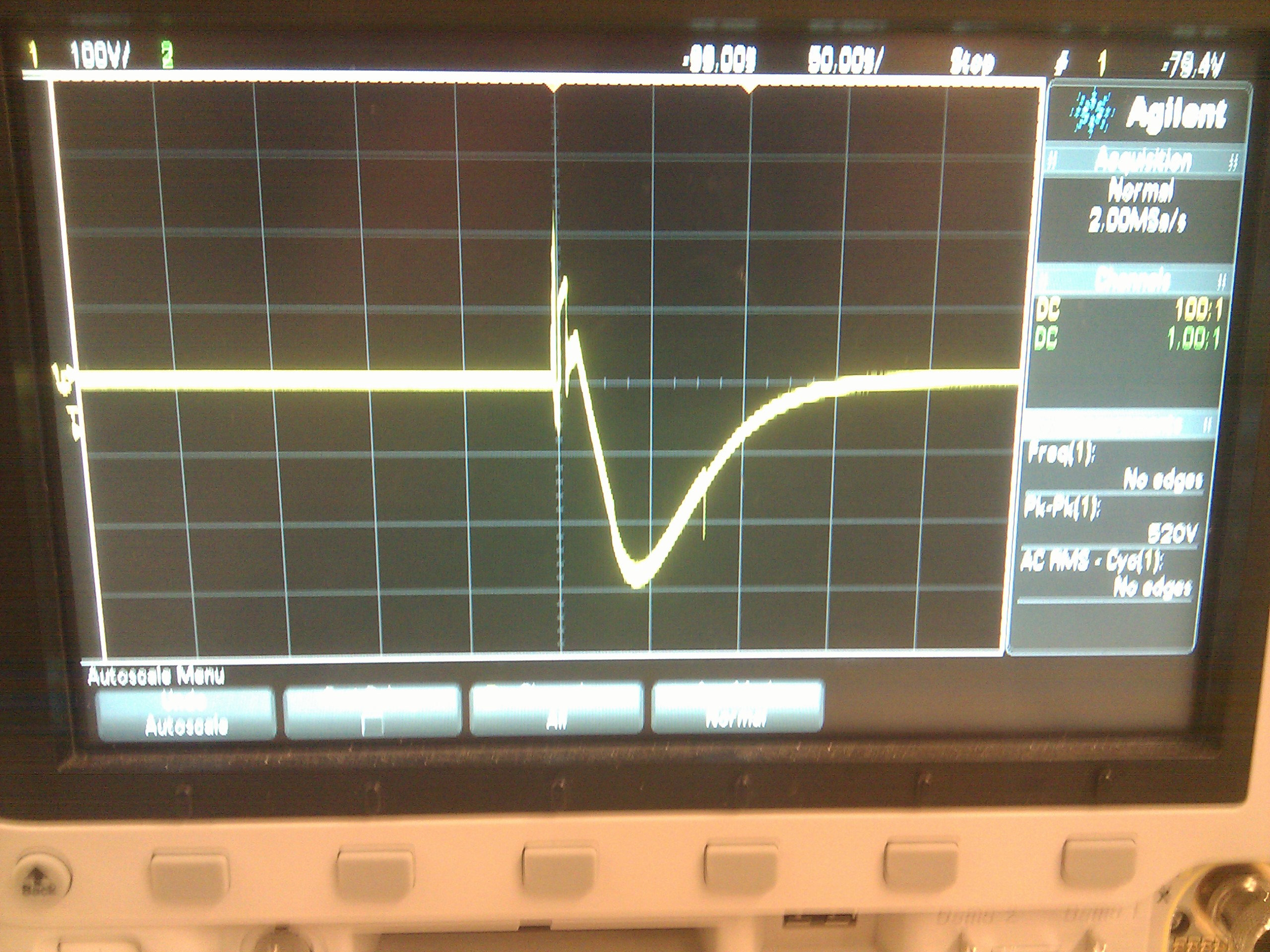
Oscilloscope screen showing high-voltage transients measured on the amplifier output during DropBot initialization. Each vertical line represents 100V.
Because the high-voltage switching boards are uninitialized at this point, high-voltage transients also appear on the outputs of all channels (though they are attenuated by roughly 50%).

Oscilloscope screen showing high-voltage transients measured on channel 0 during DropBot initialization. Each vertical line represents 100V.
These transients can cause damage to a connected DMF device (e.g., dielectric breakdown, electrolysis, etc.) if it is loaded with liquid. They can also damage the control board‘s impedance measurement (feedback) circuit if the test board is connected, since this board contains many large capacitors which provide a low-impedance path to the feedback circuit. In fact, this scenario caused us to fry several op-amps on our control board, which helped us to identify the problem.
To summarize, if the amplifier is on when you connect to the control board, high voltages may be applied to all channels in the system for a brief period (< 200 ms). To prevent damage, always make sure that the amplifier is off when you launch the Microdrop application. As an added layer of safety, you should avoid loading liquids onto your DMF device until after you have launched Microdrop. This way, even if the amplifier is on, it will not cause any damage to your DMF device or to the feedback circuit.
This problem can be addressed in future designs through hardware modifications to the control board, signal-generator board and or/the high-voltage switching boards.