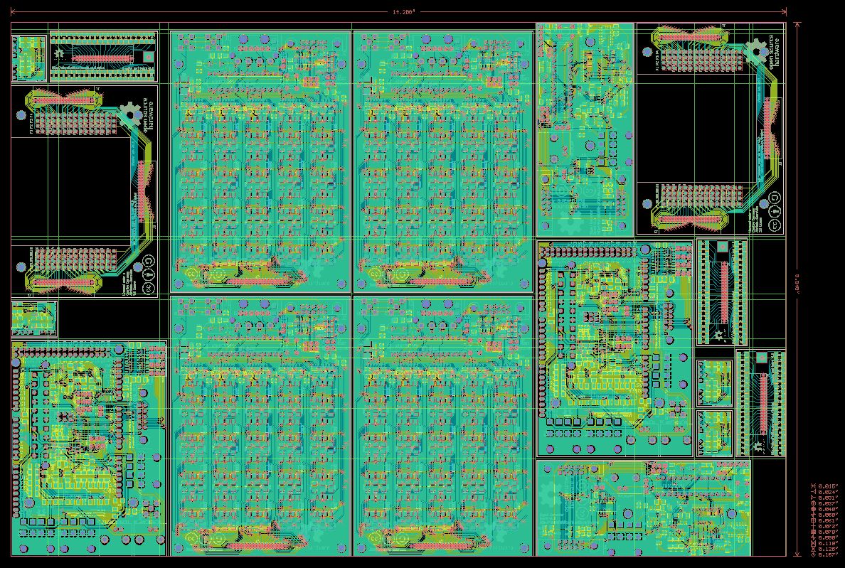
 When you’re ordering small batches of PCBs, it is often cheaper to merged the gerber files for several board designs onto a single panel. We do this using a tool called gerbmerge. If you download the electronics zip file from the wiki, it contains a sub-directory called
 merged gerbers which contains gerber files for a multi-project panel composed of several copies of the various DropBot PCBs. If you want to change the contents of this panel or it’s size, you can edit the file merged gerbers/layout.cfg.
The default panel size is 14.5″ and 10″, but you can change this by editing the lines:
PanelWidth = 14.5
PanelHeight = 10
Each board design is represented by a section in the layout.cfg file. For example, the section for the control board is included below. To change the number of copies of any of the boards in the panel, you can simply modify it’s respective Repeat = x line, where x can be any number (including 0).
[control-board]
# You can set any options you like to make generating filenames easier, like
# Prefix. This is just a helper option, not a reserved name. Note, however,
# that you must write %(prefix)s below, in ALL LOWERCASE.
#
# Note how we are making use of the ‘projdir’ string defined way up at the top
# in the [DEFAULT] section to save some typing. By setting ‘projdir=somedir’
# the expression ‘%(projdir)s/proj1’ expands to ‘somedir/proj1’.
Prefix=%(projdir)s/dmf_control_board/gerber/control-board
# List all the layers that participate in this job. Required layers are Drills
# and BoardOutline and have no ‘*’ at the beginning. Optional layers have
# names chosen by you and begin with ‘*’. You should choose consistent layer
# names across all jobs.
*TopLayer=%(prefix)s-Component.gtl
*BottomLayer=%(prefix)s-Copper.gbl
*TopSilkscreen=%(prefix)s-F_SilkS.gto
*TopSoldermask=%(prefix)s-F_Mask.gts
*BottomSilkscreen=%(prefix)s-B_SilkS.gbo
*BottomSoldermask=%(prefix)s-B_Mask.gbs
Drills=%(prefix)s.drl
BoardOutline=%(prefix)s-Edge_Cuts.gbr
# If this job does not have drill tool sizes embedded in the Excellon file, it
# needs to have a separate tool list file that maps tool names (e.g., ‘T01’) to
# tool diameter. This may be the global tool list specified in the [Options]
# section with the ToolList parameter. If this job doesn’t have embedded tool
# sizes, and uses a different tool list than the global one, you can specify it
# here.
#ToolList=proj1.drl
# If this job has a different ExcellonDecimals setting than the global setting
# in the [Options] section above, it can be overridden here.
#ExcellonDecimals = 3
# You can set a ‘Repeat’ parameter for this job when using automatic placement
# (i.e., no *.def file) to indicate how many times this job should appear in
# the final panel. When using manual placement, this option is ignored.
Repeat = 2
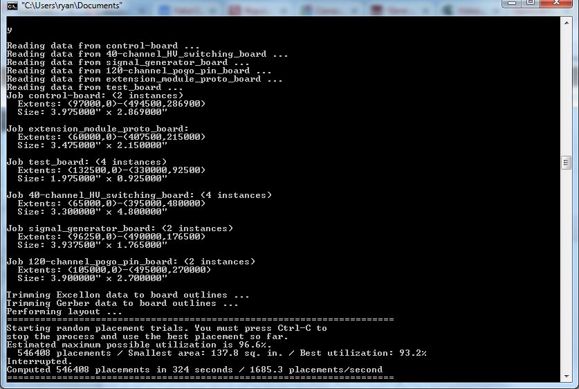
Once you’ve made your modifications to the layout.cfg file, open a command terminal (press the Windows Key + R, type “cmd”, and press ENTER) and navigate to the merged gerbers directory. Now type “gerbmerge layout.cfg” and press ENTER.
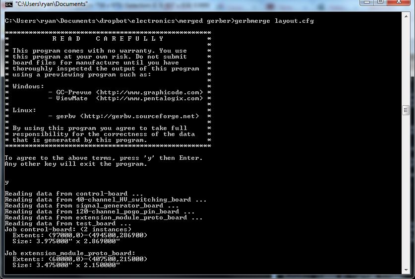
Follow the instructions on the screen (i.e., type “y” and press ENTER). Then the gerbmerge program will read in the gerber files for each of the projects and attempt to place them on the panel. It will keep a running count of the number of placement attempts and the panel area. Once you are happy, you can press CTRL + C to stop the process. If the program cannot fit the designs onto the defined panel size, you will need to go back and modify the layout.cfg file (either reduce the number of designs or increase the panel’s dimensions). For more information on viewing the resulting gerber files and ordering PCBs, refer to the BuildInstructions.

 About a month ago, we received an email from Markus Haapala from the University of Helsinki with
